EEGoSports
This page describes the installation and usage of the EEGoSports driver plugin for MNE Scan.
Building the EEGoSports Plugin
In order to build the EEGoSports driver plugin, the eemagine folder from the SDK has to be added to the EEGoSports folder in the mne-cpp repository in a first step. This location can be found in the mne-cpp repository under:
\mne-cpp\applications\mne_scan\plugins\eegosports\
The eemagine folder includes another folder called sdk which holds the necessary header and source files like: amplifier.h, buffer.h, channel.h, exceptions.h, factory.h, stream.h, version.h, wrapper.cpp and wrapper.h.
In a second step, the eegosports subproject has to be reintegrated into the mne-cpp project. This can be achieved by adding MNECPP_CONFIG += withEego in the mne-cpp.pri file.
Now, the whole EEGoSports plugin can be rebuilt. MNE Scan will then contain the EEGoSports plugin in its Sensor plugin section.
Running the EEGoSports Plugin
For a correct recognition of the EEGoSports device, the operating system compatible driver has to be installed with the delivered software. Furthermore the two files eego-SDK.lib and eego-SDK.dll from the driver’s library have to be copied to the location:
\mne-cpp\out\Release\apps\
In a last step, for older SDK versions the license files which are delivered with the device have to be copied to
C:\Users\Username\Documents\Eego
The license files should be named like EE225-020032-000001.
For recent versions of the SDK, this step is not necessary.
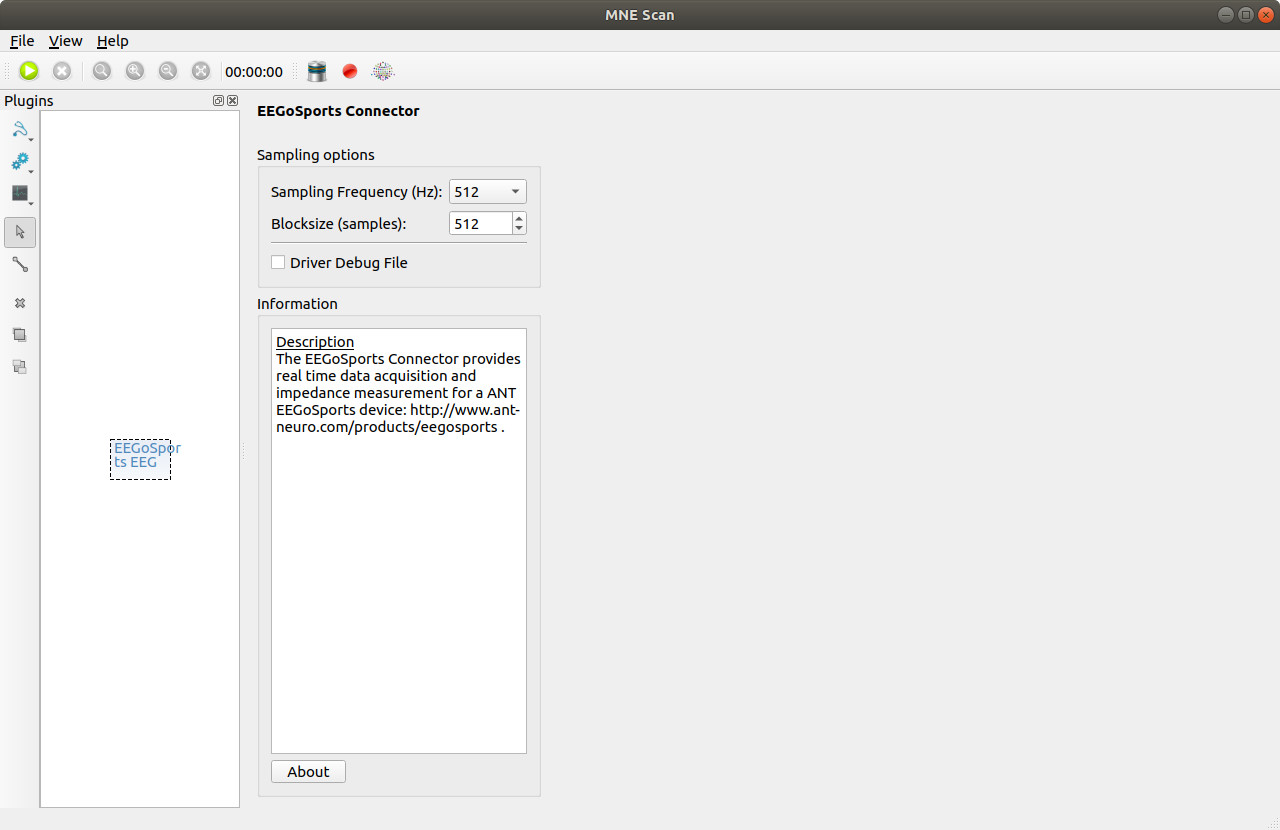
After that, the device can be connected to the computer and be switched on and MNE Scan can be started. It is now possible to use the EEGoSports plugin in the MNE Scan environment. Via drag & drop the plugin can be added to the plugin box and connected to other processing items like shown in the following figure.

The GUI of the EEGoSports EEG plugin allows the adjustment of sample frequency and block size. A FIFF-data-stream is now streamed to the real-time display and subsequenty connected plugins.
Besides the electrode measurements, the FIFF-data-stream additionally contains one channel for the reference electrode, the trigger channel, and the sample count channel.
Impedance Measurements
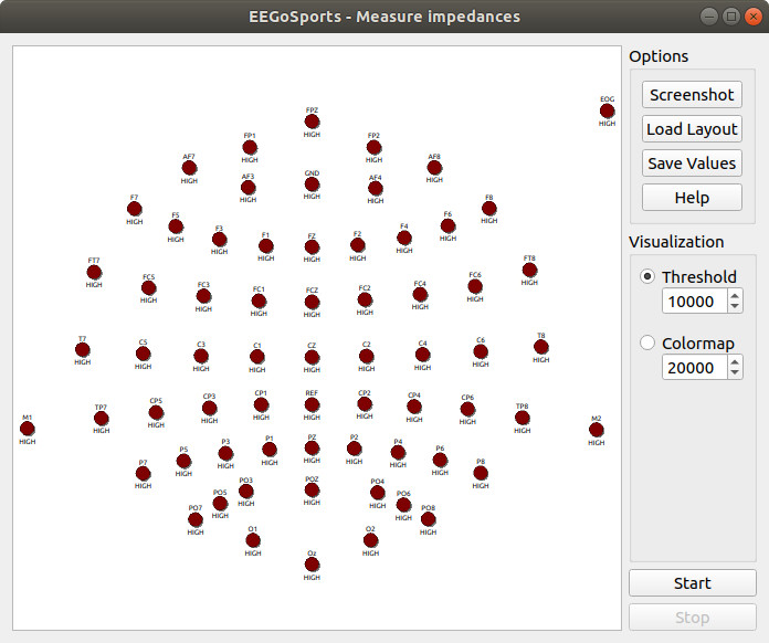
Selecting the ![]() symbol opens the widget for impedance measurements.
symbol opens the widget for impedance measurements.

To display the electrode positions, the correct electrode layout has to be loaded via Load Layout. This file has to be in the ELC format and must contain the electrode labels and positions in the order, in which they are transmitted to the amplifier (see amplifier/eeg cap documentation).
At the end of the list of electrodes, the positions of reference and ground electrodes should be added with the labels REF and GND.
Two options exist for the color coding of the impedance values:
-
For
Threshold, green color indicates an impedance value below the selected threshold, yellow color an impedance value below double the selected thresold, orange color an impedance value below three times the selected threshold, and dark red color an even higher impedance value. -
For
Colormap, the electrodes impedances are color-coded following aJetcolormap with the maximum of the colormap at the selected value.